Week 3: Computer Controlled Cutting
In this third week of Fab Academy, I need to get acquainted with Vinyl Cutting, Laser Cutting and also have to complete a group & an individual project. The tasks for this week are:
- Design, lasercut, and document a parametric press-fit construction kit, which can be assembled in multiple ways.
- Demonstrate various results using images and videos but in compressed format to save space
- I need to install various softwares and troubleshoot them if necessary
- Need to include orginal design files, analyze various parts if possible & explain my learnings in layman language
- Learn how to use Laser Cutter, Learn machine parameters, Learn about Kerf and make kerf scales for various materials in our lab
- Learn how to use Vinyl Cutter, Learn machine parameters, learn how to use vinyl cutters using Mods interface and cut a design on vinyl sheet
The following are the softwares that I have used for learning various operations:
- Inkscape : Vinyl Cutting, Laser Cutting
- MIT Mods : Machine Management
- Rhino : Laser Cutter
- Job Control : Laser Cutter Software
| |
|
|---|---|
| Wednesday | Prof. Neil's class, Computer Controlled Cutting |
| Thursday | Inkscape, Vinyl Cutting, MIT Mods |
| Friday | Laser Cutting - Class interrupted due to Covid |
| Saturday | Laser Cutting - Documentation |
| Sunday | Laser Cutting - Documentation |
| Monday | Laser Cutting - Parametric Design - Research - Class interrupted due to Covid |
| Tuesday | Laser Cutting - Kerf Bend - Parametric Modelling - Class interrupted due to Covid |
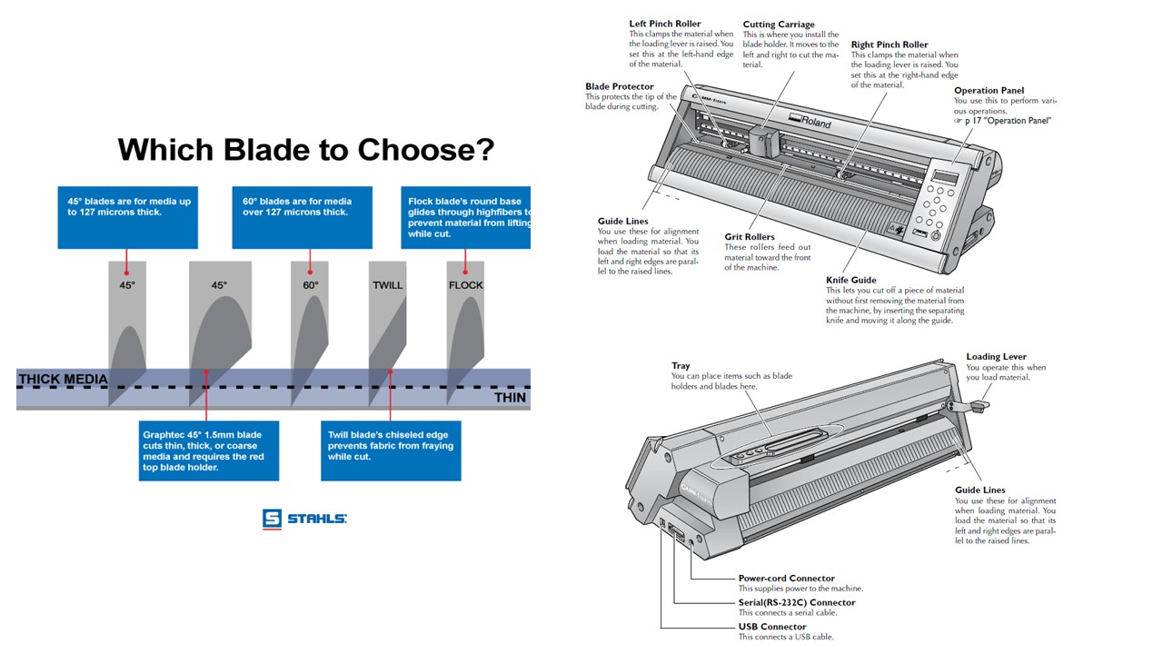
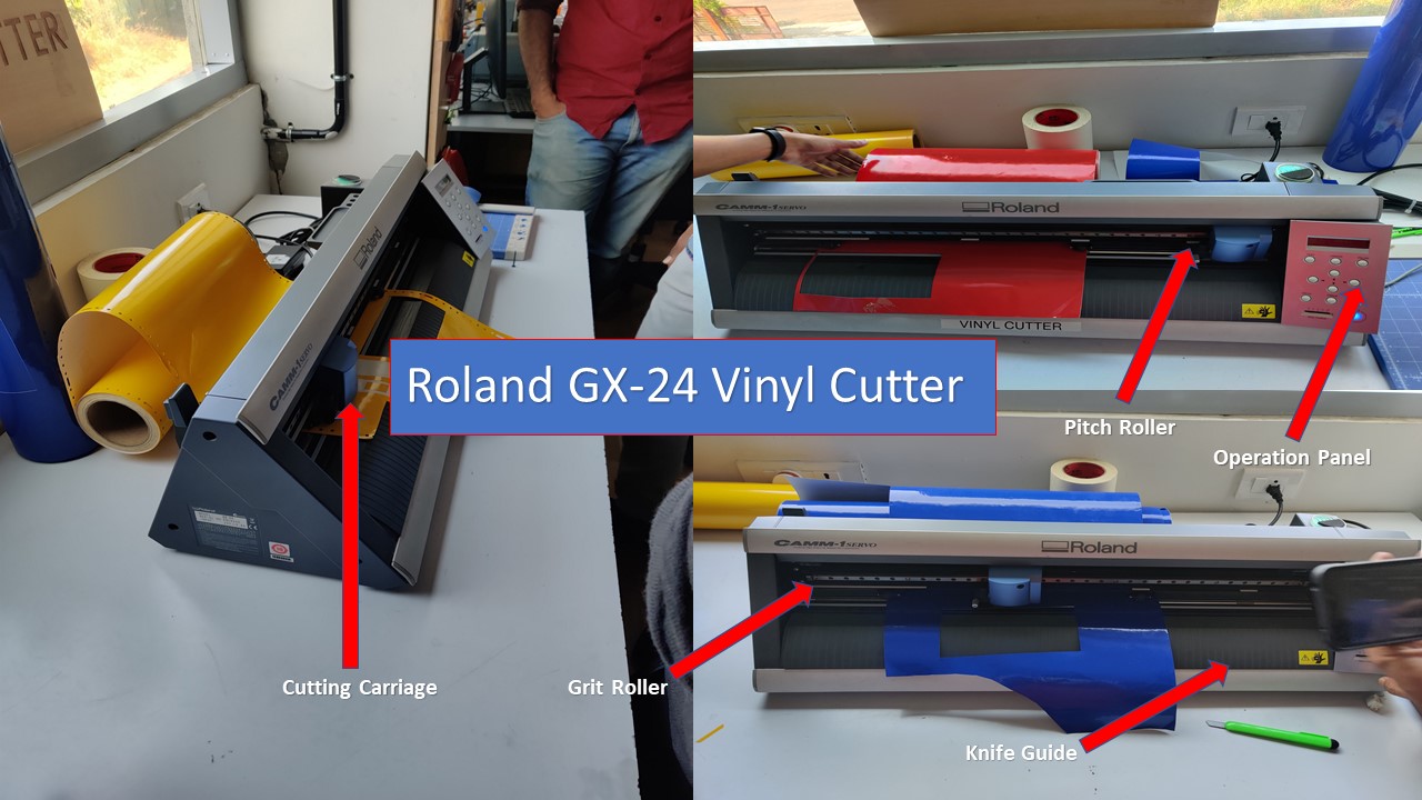
The Vinyl Cutter is a dope machine which is used to make stickers, used for t-shirt printing etc. The Vinyl Cutter available in my lab is the Roland GX-24 it has got a bed length of 610mm. The Vinyl cutter uses computer controlled blade to cut out shapes and it works on the basis of caster angle. It has a knife which is mounted on a CNC arrangement for linear motion. The knife can rotate on its axis and the bed has rollers for moving the sheet back and forth. The sheet is cut by moving knife over it. We can set the cutting velocity and cutting force depending on the material of the sheet we are cutting. Vinyl cutter consists of a moving head, a gap to place the vinyl sheet and few rollers which helps the movemnet of the sheet. The Roland vinyl cutter has the advantage that the blades can be changed depending on the work to be done. The angle of the cutting blades is a factor to consider. In the lab, the blade used has an angle of 60º and they are hard but brittle. The most common angles are 30º, 45º and 60º. The specification of the machine is as follows:
| Software | Inkscape + MIT Mods |
| Maximum cutting area | 584 x 24998 mm |
| Cutting speed | 10-50 mm/s |
How to setup the Vinyl Cutter
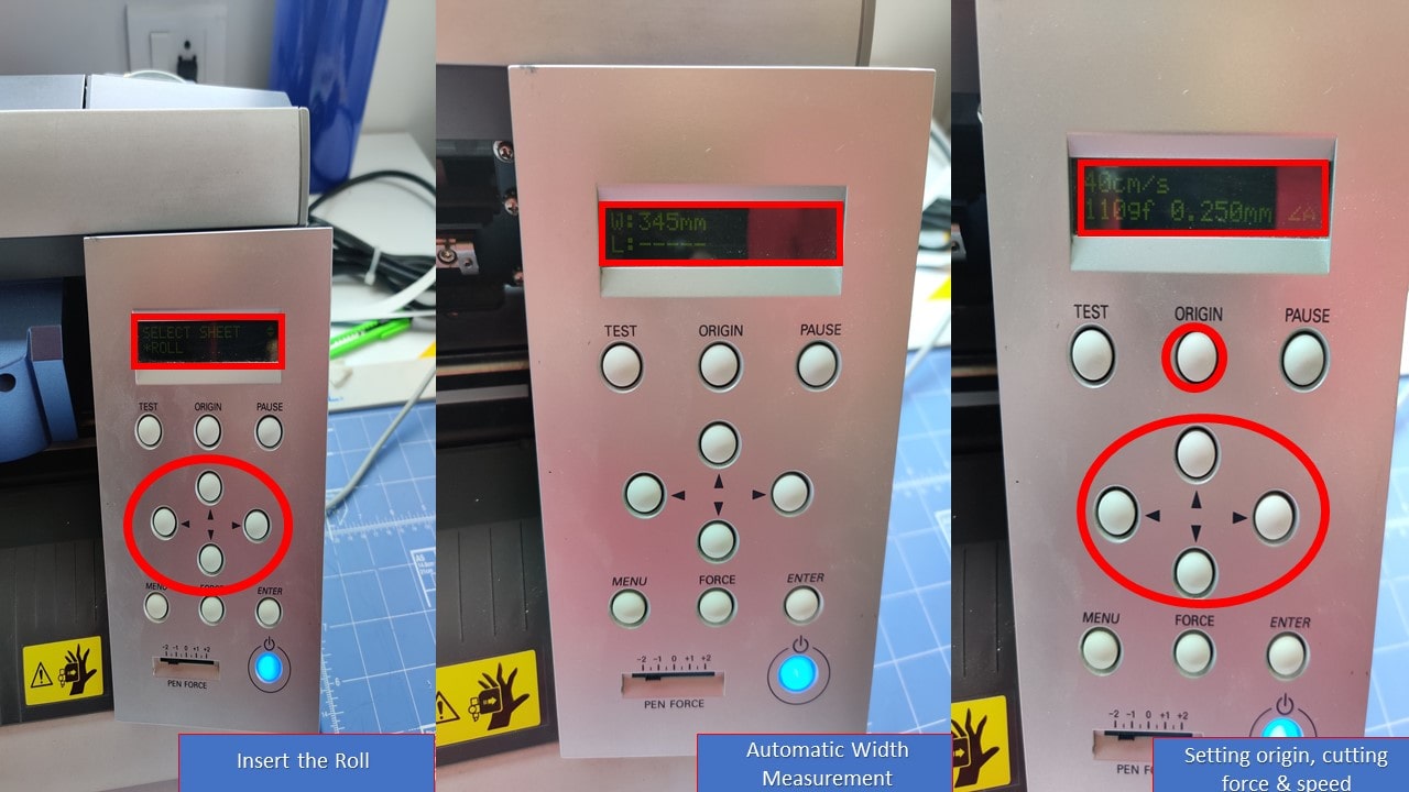
- First, the Pinch roller is released and the material is loaded manually through the Grit Roller
- Next, it is ensured that the grit rollers are right above the markings and the pinch roller is locked into position
- With the help of navigation buttons in operation panel, the material is moved to required location
- The machine then automatically takes the width of the material and diplays it in the screen
- Now the origin is set using the button and a trail cut is conducted to check the velocity and force
- Once the cutting is over, the material is then removed using a knife swept through the knife guide
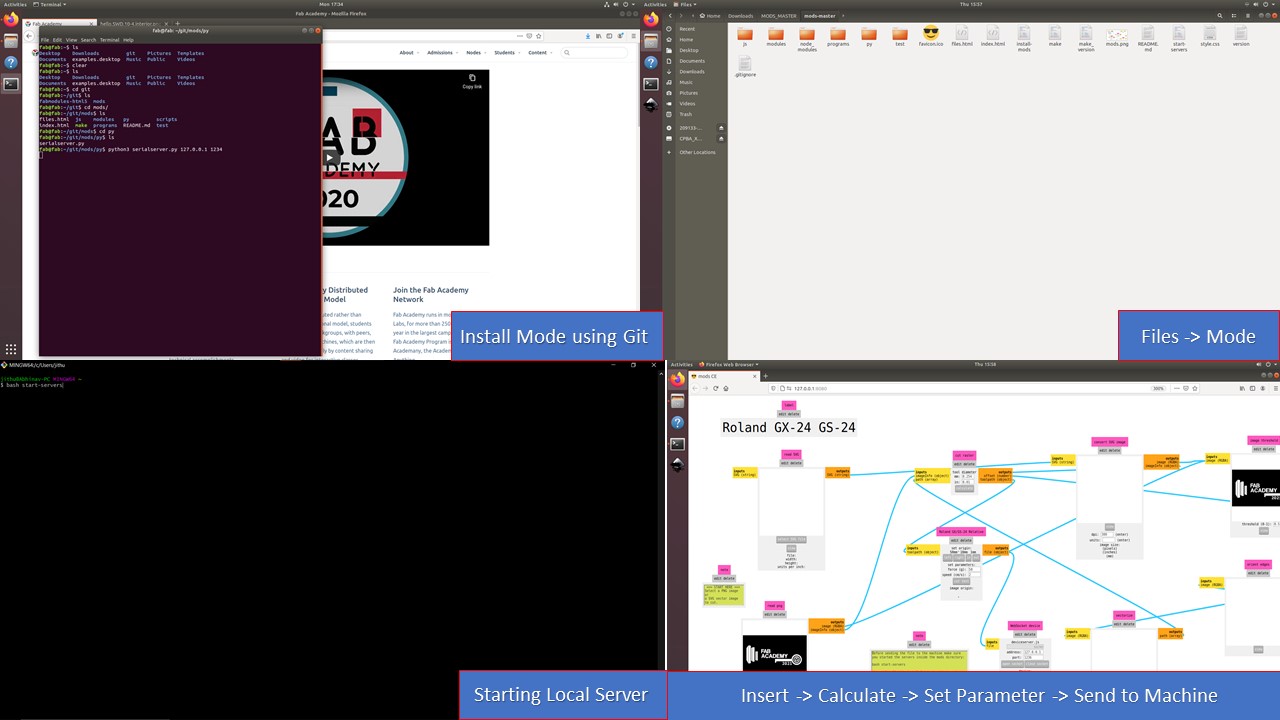
Even though softwares like Rhinoceros is available with Roland Drivers, my lab went with MIT Mods and I am very much amazed with the simple interface of the software. Mods community edition is a fork of CBA mods research project. mods is a modular cross platform tool for fablabs. It is based on independent but interrelated modules.Mods could potentially be used for CAD, CAM, machine control, automation, building UI, read input devices, react to to physical models, and much more. The following are the steps involved in installing Mods in the computer using terminal :
How to setup the Mods
- First, you need to install Mods using Git Bash
- Next, you need to type inside the mods file directory to start it
bash start-servers
- Now, you need to select Roland GX-24 and need to upload the PNG file
- Further, you need to run the calculation and need to setup velocity and force (40 cm/s & 110gf)
- Since the parameters are change now you need to close and open the socket
- Finally, you need to run the code by clicking button called
Send File to Device
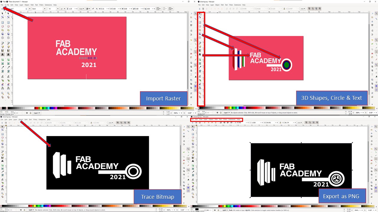
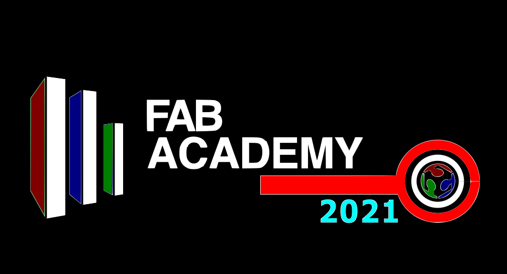
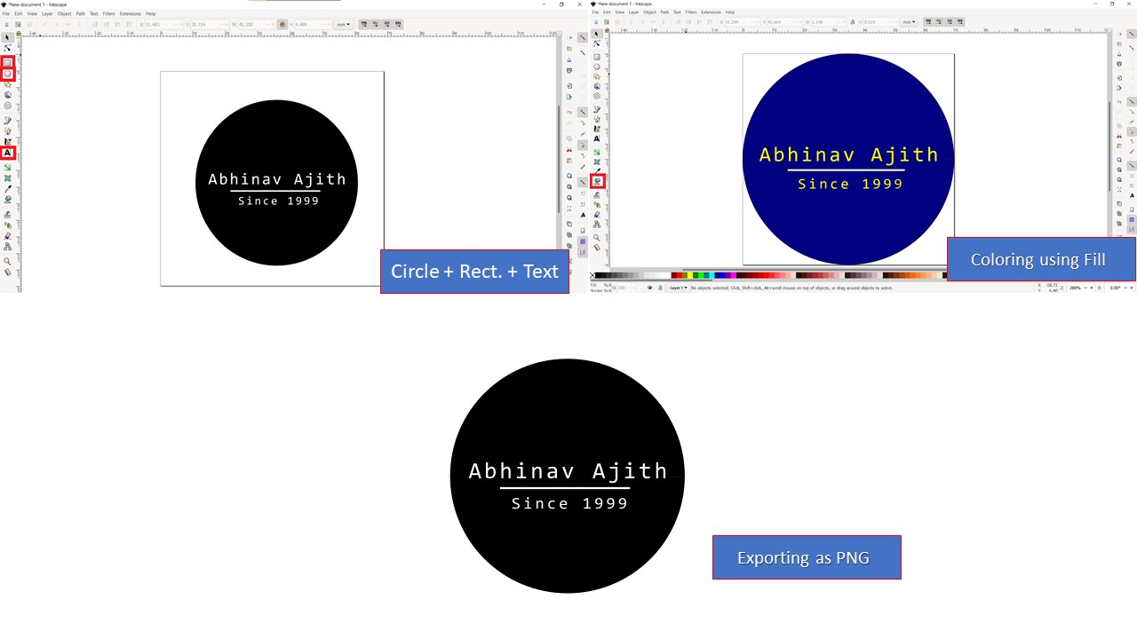
The Roland Cutter only accept vector based images and the inkscape is used to convert raster to vector using trace bitmap feature. Here my idea is to create a logo for Fab Academy 2021 incorporating various elements from CBA & Fab Foundation. The following are the steps involved to conduct Vinyl Cutting using Inkscape :
- First step is to import the raster image using File -> Import tool
- Next you can add shapes and text if required using the menu bar present in left corner
- Now the raster images can be converted to vector by going to Path -> Trace Bitmap
- Suitable brightness threshold is selected and the bitmap is traced
- Next, you need to resize the page by going into File -> Document Properties - > Resize based on images
- Finally, the vector image is imported as PNG using export tool found in the files
The PNG image is then imported in Mods and is fed to the Vinyl Cutter

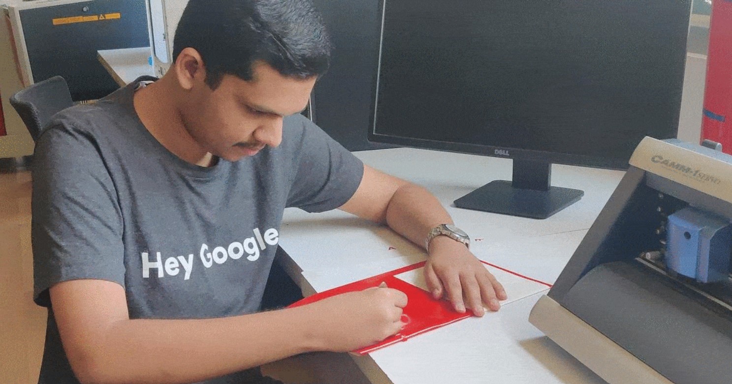
To make the task interesting, I thought of making a custom sticker for my laptop. The process was quite simple since I didn't import any Raster image. A simple logo was made using circular, rectangular & text options available in the menu bar. Like previous one, I had cut the logo using Vinyl Cutter and stuck a yellow vinyl sticker just behind the blue one. Even though the process was quite simple, I feel the colour contrast is awesome and it matches well with my laptop.
Mistakes made:
- The font size was small so it was very difficult to remove the sticker using forceps
- I haven't used any tape to remove the main sticker so the text was torn in between and I had to compensate by manually cutting a piece of vinyl
- Due to lack of time and resources, I couldn't test out a flexible sticker ( I will do it when I find time)
- During the first attempt, when I tried to import SVG file for Mods, it didn't show up since the font was missing in the Inkscape version where I hosted Mods
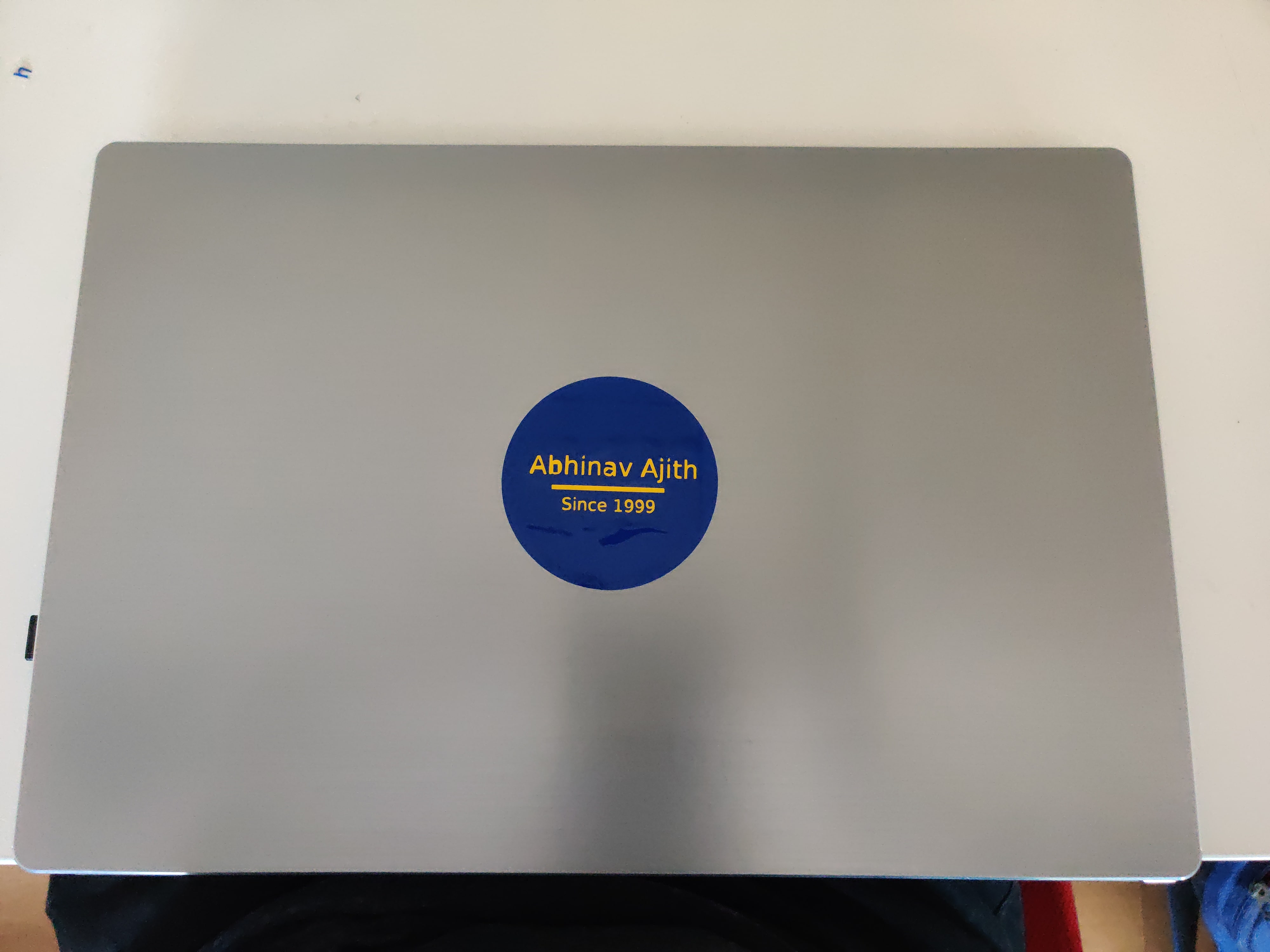
Since the letters were to small, it was very difficult to remove it from the Vinyl sheet and I accidently damaged it during the process. So I was left with the blue vinyl sheet and I had used a rectangular yellow vinyl sheet from the leftover print to fill the gaps under the lettering.
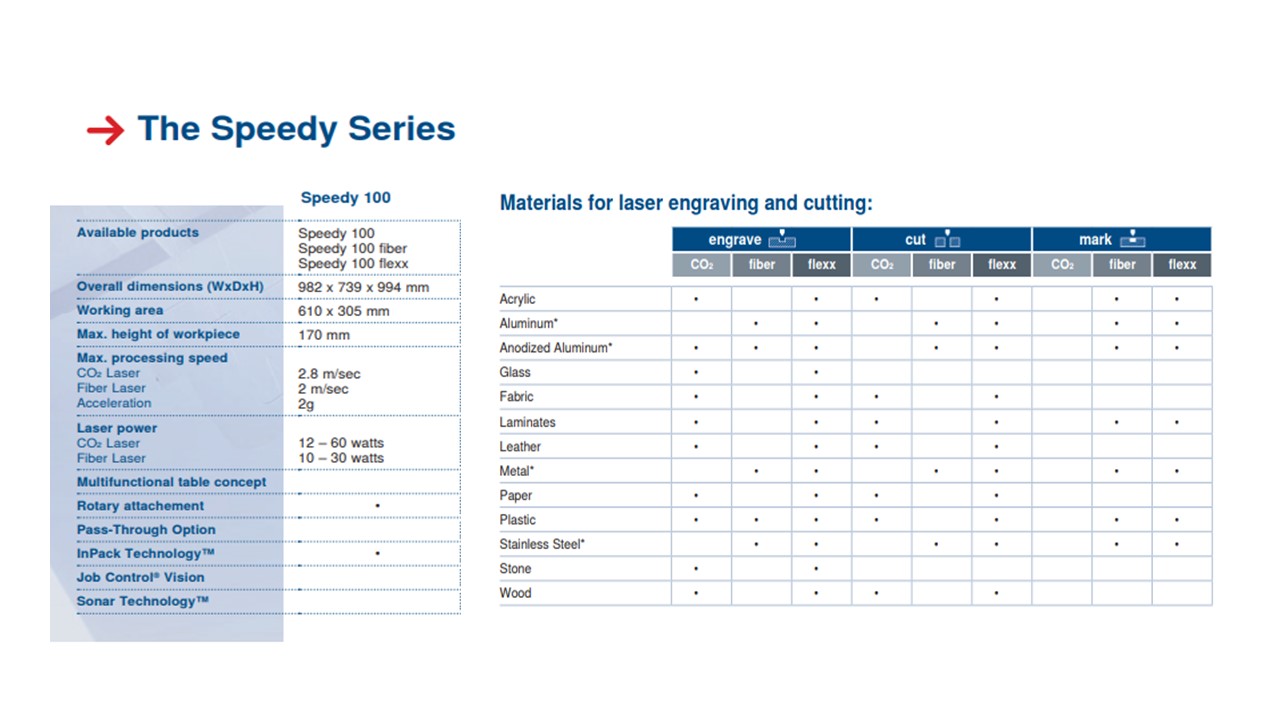
Laser cutting is a technology that uses a laser to slice materials. While typically used for industrial manufacturing applications. Coined from the words Light Amplification by Stimulated Emission of Radiation lasers have been a byword for efficiency and quality in materials processing since their advent in the sixties. Able to heat, melt and even vaporise material, lasers are seen as the ideal medium for channelling intense but controllable energy. A commercial laser for cutting materials uses a motion control system to follow a CNC or G-code of the pattern to be cut onto the material. The focused laser beam is directed at the material, which then either melts, burns, vaporizes away, or is blown away by a jet of gas,leaving an edge with a high-quality surface finish. The Speedy 100 has a 40 W carbon dioxide laser capable of cutting through wood, paper, and acrylic. The high energy beam generated in the chamber is directed at the work place through a system of prisms moving in a CNC arrangement. Since the material removal takes place by vaporization, care should be taken when cutting flammable materials kike paper and wood. The fumes produced in the laser cutting is sucked out through a seperate apparatus. These are the common terms used in Laser Cutting:
Laser cutting : This is the process of cutting a shape to create smaller sizes, pieces, or more complex shapes.
Laser engraving : Engraving is the process of removing a layer of a material to leave an engraving below. This is often used for etching barcodes onto items or personalising items.
Laser marking : Marking is similar to engraving in that a mark is made but the difference being that the mark is only surface level, while an engraving from laser engraving has much more depth.
Laser drilling : Drilling is the process of creating dents or thru-holes on or in the surface of a material.
Laser power, P : They can be set as a percentage between 0 and 100%. 100% is maximum power. For dark wood engravings or stamp engravings, you generally need high power, whereas low values are used for materials such as paper.
Cutting Speed, v : The Speed laser parameter describes the movement of the laser head. Fast speeds lead to short exposure times, slow speeds lead to long exposure times. For example, large-scale engravings of TroLase materials are engraved at high speeds between 80% and 100%, but for photo engravings with lots of detail on wood, the speed should not exceed 10%. This setting also affects the quality of the laser cut.
Number of Passes, n : The Pass parameter determines the number of engraving or cutting passes. With some materials, for example, it can be advantageous to engrave with lower power and high speed, and then repeat this process several times. This means that the material is less stressed per pass. For example, this approach is appropriate for a relief engraving.
Pulse frequency : As with the laser power, the pulse frequency can be matched to the relevant machining task. For example, it is recommended small contours are cut with reduced pulse frequency. The pulse frequency is also reduced when piercing in the ramp mode.
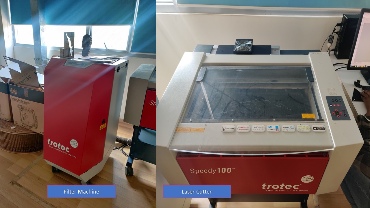
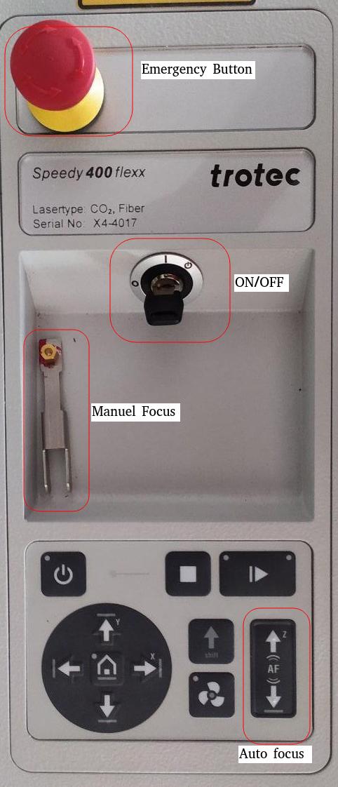
The laser cutter that is available in our FabLab is a Flexx trotec speedy 400. This laser cutter has two types of laser- CO2 and glass fibre laser. The laser cutter has two types of laser - CO2 and glass fibre laser. for our use we only need the CO2 laser. It has a 60 watt CO2 laser, 30 watt fiber laser, with a work area of maximum 610 mm by 305mm. In order to start working with it, we first turn on the laser cutter (the switch is clearly labeled), followed by also switching on the separate ventilation system. To interact with the laser cutter we used which is installed on the desktop that is next to the machine. The Flexx line of laser cutters has both CO2 and fiber laser technologies: The fiber laser enables us to engrave the copper layer of the FR1, and once it has been removed, we can cut the board with the CO2 laser. The specifications of the Trotec Laser Cutter is as follows:
| Laser type | CO₂, Fiber or Flexx laser |
| Maximum cutting area | 610 x 305 up to 1016 x 610 mm |
| Max. workpiece height | 125 - 305 mm |
| Laser power | 10 - 120 watts |
Safety Practices to be followed while using a Laser Cutter
- The machine must not be left unattended while it is operating (supervised operation).
- Switch off the machine at the main switch for periods of non-use.
- Operate the machine described here only with a lens in place.
- A missing lens may cause the unfocused laser beam to be reflected out of the housing.
- Stop this machine immediately in case of failure.
- When pressing an Emergency stop button, the electric circuit immediately shuts off.
- The laser beam is interrupted, and all movements are stopped.
- The function of the Emergency stop button is: Firstly: To prevent any risks to the operating personnel. Secondly: To avoid any damage to/destruction of the machine/material
- Turn the Emergency stop button counterclockwise to unlock it (green marker is visible). 2. Reboot the laser system with the help of the key switch.
Setting up the Machine
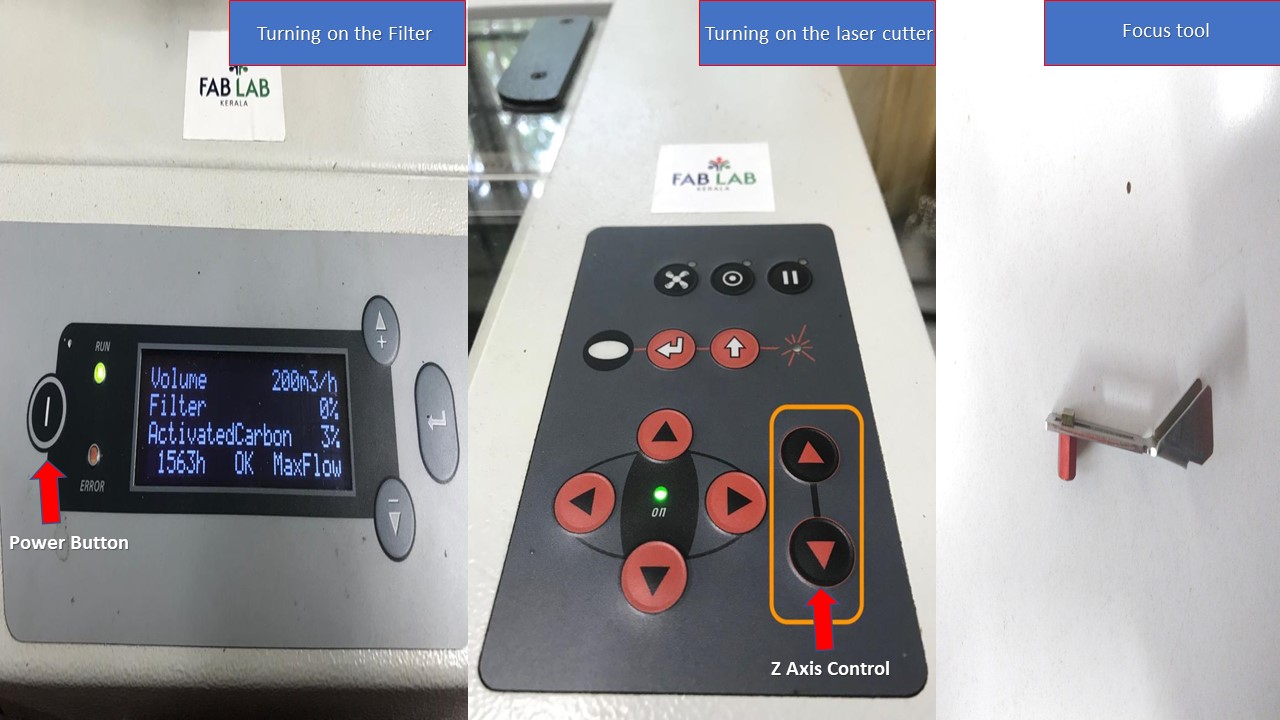
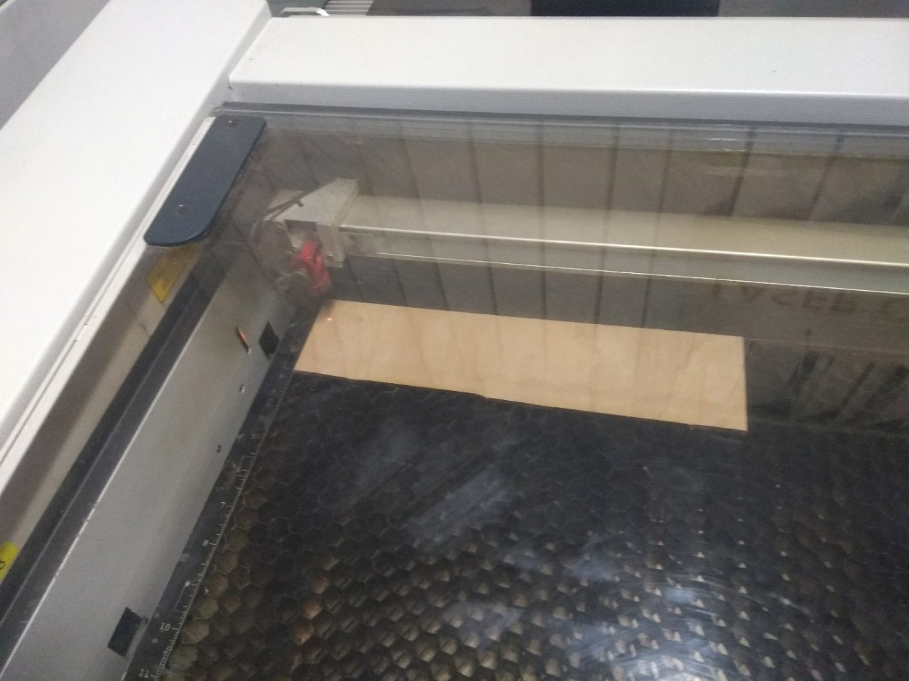
- The very first step is to turn on the laser machine and the filter machine and the material is placed inside the laser cutter. It should be ensured that the material is properly placed.
- The next step is to focus the laser. For this there is a focusing tool available with the machine. This is placed on a small groove in the Laser and the bed is raised using Z axis control button in machine panel until it touches the tool. The tools drops from the groove when the bed touches it indicating that the laser is now focused. This step is important because if the Laser is not focused properly it may not make a precise cut or it may burn the workpiece. Once this is done, the lid is closed and the cut is made. Acutally there are 4 different ways to focus the laser and my lab has opted for the focusing tool technique since it's fast and flexible. The details about other methods can be found here: Trotec Laser Focusing
- The focus is now confirmed and next step is to move the effector to the desired location. This can be done by manually moving the effector in X & Y axis using machine control pad. Once this process is complete I can now start laser cutting. Yaay!
These images depict various steps mentioned above.
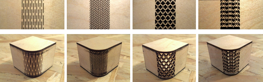
Kerf bending is a method where many slots are cut into wood to create beams and are capable of bending. Where these cuts turn the solid piece of wood into a series of interconnected beams, and these beams bend by torsion. They are also called as living hinges and there are plethora of designs available which includes: dashed pattern, herringbone pattern, midevil cross pattern, diagonal cross pattern, space invaders etc.
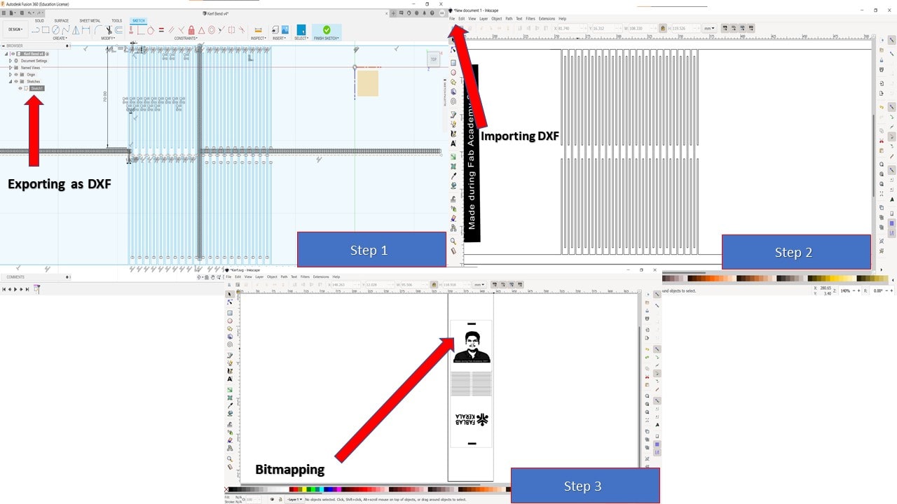
Instead of using a template, I had tried to make a dashed pattern in Fusion 360 and wanted to test the results. The steps involved are as follows:
- First, by referring to various resouces I had created a dashed pattern using simple sketches, mirror operation and dimensioning in Fusion 360
- Once the pattern is completed, I had exported it as DXF by right clicking the sketch from the browser
- The DXF file is then imported to the Inkscape and various other elements are imported depending upon the requirement
- I intend to build a photoframe with my picture on one side, for that I had imported and bitmapped the image.
After exporting the file as dxg format from Inkscape, I had imported the image in Rhino. For engraving I had provided black color and for red color it's cut. The kerf of laser for wood was found out via test and the kerf value was found to be 0.15 and power was chosen 0.5cm/s. Then it was exprted to Trotec software for print and followed the previous steps. The follwing videos depict the engraving and cutting operation.
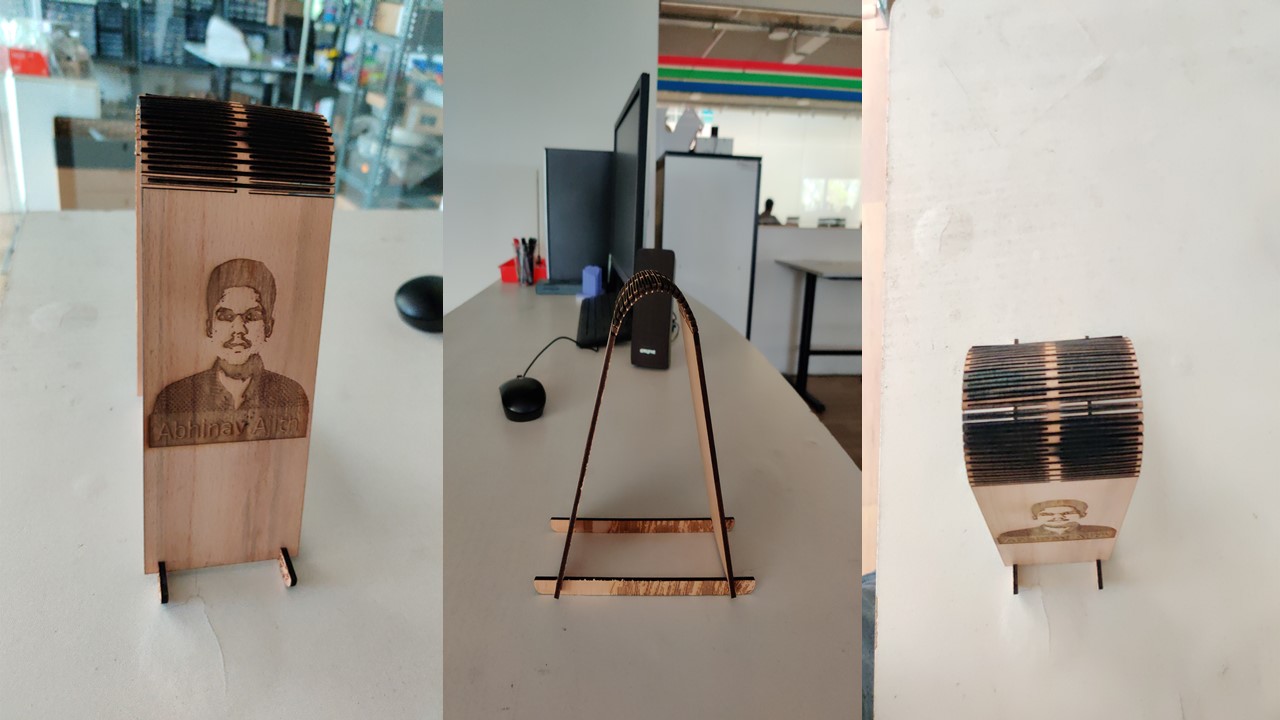
Hurray, the kerf bend was obtained as expected.
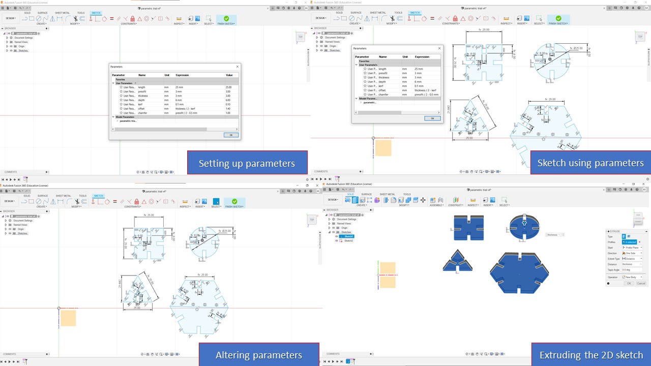
The main assignment for this week was to create a parametric press fit design. Paremetric designing in modelling means giving constraints to geometrical dimensions or setting user parameters while designing. When a user parameter changed or modified then the entire geometry shape will get changed. The tools is very useful for designers and it gives the freedom for the user to modify the final model based on parameters. At first, I was confused about this whole process and since my lab was closed due to Covid, I didn't get a chance to learn from the instructors. So, finally I took the courage and I had referred a lot of previous Fab Academy archives and atlast found how to use the parametric design. The following are the steps involved in parametric design:
- First of all, I need to decide the parameters which has a possibility of modification. For my model, I had chosen length, thickness, pressfit, depth, kerf, offset & chamfer
- For adding parameters, I need to go to
solid -> menu bar -> modify -> change parameters
where I need to add user parameter with name, value and a comment (if needed) - Once, the paramters are fixed then I need to create 2D sketch using parameters or use a combination of mathematical operations on parameters.
- Finally, I can check the parametric design concept by varying the value of parameters and observing how the model changes with respect to it
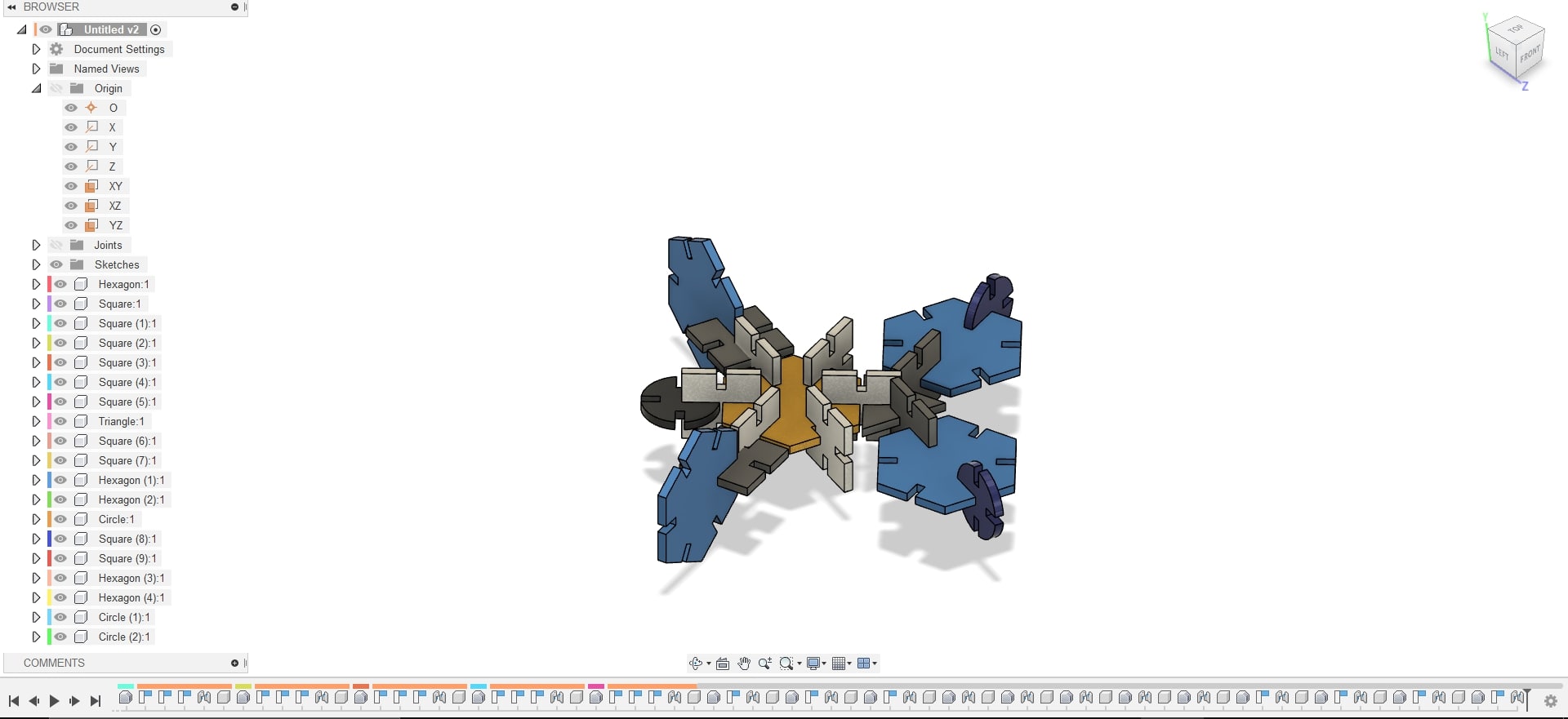
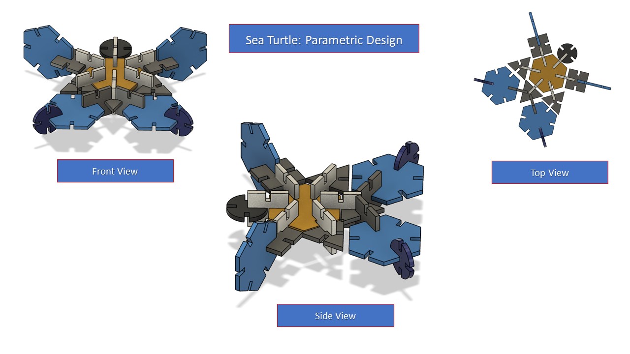
Parametric Construction using Fusion 360
Since I am proficient in Fusion 360, I chose it to model the parametric contruction kit. Even though I was confused about what to make, I finally had an idea to make a sea turtle model by using 4 basic shapes: square, triangle, hexagon & a circle. As mentioned earlier, I had setup the parameters and I used dummy values for kerf, offset & chamfer since I didn't have access to the laser cutting machine. When I initially modelled, the triangle's middle portion was small and my indtructor asked me to change it since we are using cardboard for parametric design so, I made the triangle bigger to enhance strength. After 2D sketching, I had extruded based on given thickness of the carboard. Since, I couldn't laser cut due to the closure of the lab, I though of making an assembly in Fusion 360. For that I had used "Joint" contraints in faces and had also provided color to make it more appealing. I didn't import the sketch to inkscape since I was not laser cutting, so I settled with the assembly. The various steps are depicted below:

Steps involved in Laser Cutting
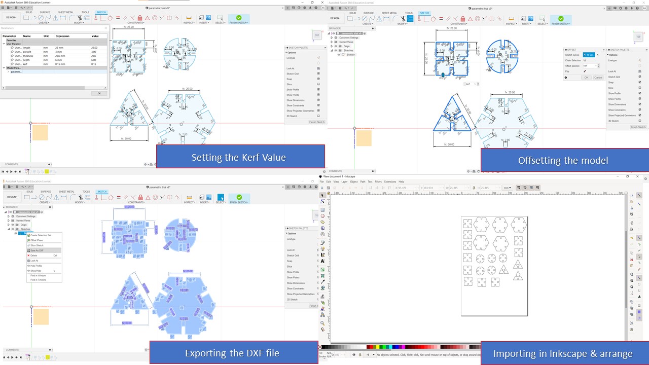
- The first step is to modify the kerf value with the value that you had found using the kerf tool made out of laser cutting. The kerf is then added to the sketch by using offset feature from menu bar.
- The next step is to export the sketch as DXF file by right clicking the sketch from browser and exporting it. The exported file is then opened using Inkscape and required copies are made and arranged depending upon requirement
- Once this step is completed, the Inkscape file is again exported as DXF to feed into the Rhino software which is used for Laser Cutting
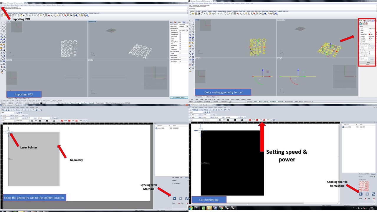
- The DXF is imported using Rhino and is colour coded in red to define the cut feature. Do not that you need to provide the line type as continuous, print color as red.
- The file is then print using the print command in Rhino as if fed to the Trotec software. In Trotec software, at first we need to click Ready to synchronise software with the laser cutter
- The number of passes are defined using material proporerties menu from menu bar and the speed and power is set to required values depending upon the material. Here I used 100% for power & 2cm/s as speed
- In the mean time, the cardboard (Material) is loaded into the laser cutter, focussed using tool, filter is turned on & finally the send button is clicked in Trotec software thereby staring the cut
- The video provides the details about the cutting process & once completed, the parametric kit is assembled to resemble the predicted model of the sea turtle
- Based on my experience, there was a lot of fire happened during the cut and had to retry a lot of times to get the final cut. Moreover, I once forgot to turn on the filter which caused a little suffocation at first
- Later, I found that I need to make the geometry as a group before exporting to reduce the number of passes which went more than 2 and had created the fire
- The final kit was satisfactory considering the strength of cardboard and the triangle geometry was found to be a bit small and had created press fitting issues during the assembly
- I was happy to make an interesting model and was appreciated by the instructors.


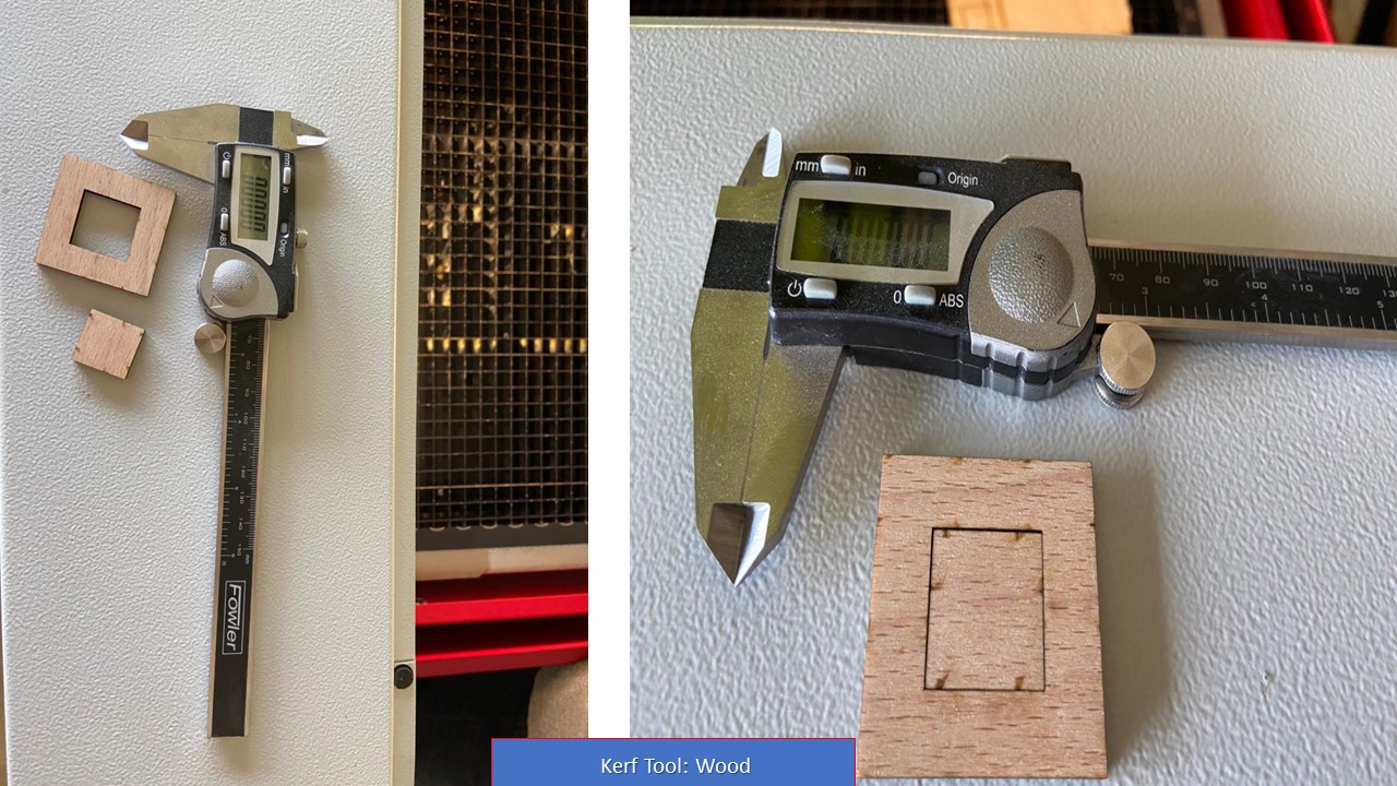
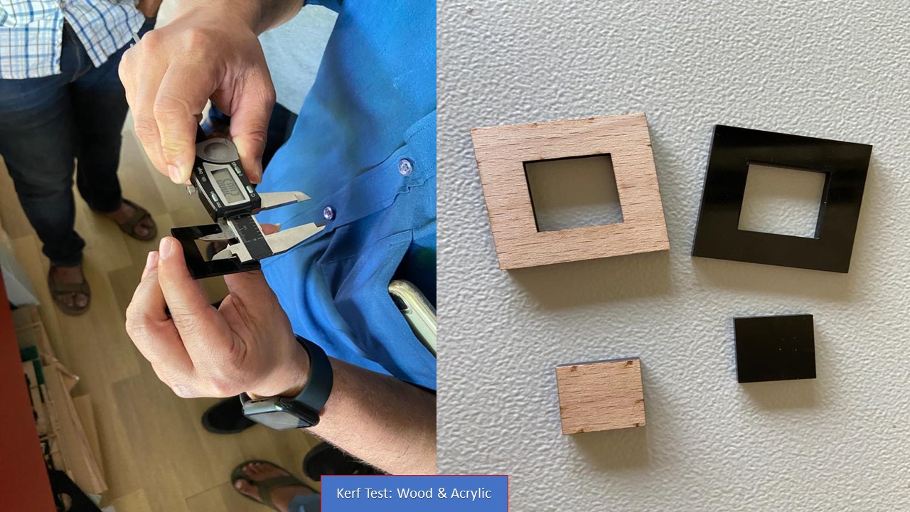
Group Assignment: Kerf Scale
The laser burns away a portion of material when it cuts through. This is known as the laser kerf and ranges from 0.08mm – 1mm depending on the material type and other conditional factors. Although above c0.45mm is only experienced when cutting thicker foams. Any areas in our design where cut lines come closer than 0.5mm together could burn away entirely. Any details narrower than 1mm are likely to be very fragile and in some cases can cause the material to warp whilst cutting. As a benchmark, the recommended minimum cut widths be no smaller than the corresponding thickness of the material. For example, if cutting from 3mm acrylic, it’s best not to allow any widths less than 3mm. We can go smaller but this can make your pieces very fragile which might not be suitable for our application. Kerf is determined by material properties and thickness. But other factors also have an impact on how much the laser takes away. The focal length of the lens, pressure of compressed air both have an impact. Kerf widths can vary even on the same material sheet, whether cutting a straight line or a curve line or from laser cutting in the x or Y dimension. The manufacturing tolerance of the material can also impact the kerf.
Test Cut
Parameters:
- Power
- Velocity
- Frequency
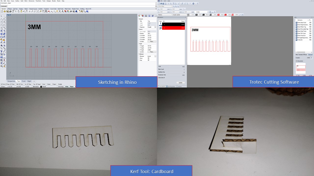
For 3.4mm Cardboard
| Power | 20% |
| Velocity | 20 |
| Frequency | 1000 |
| Kerf | 0.23mm |
For 3.83mm Brich Wood
| Power | 75% |
| Velocity | 80 |
| Frequency | 1000 |
| Kerf | 0.15mm |
For 1.8mm Acrylic
| Power | 75% |
| Velocity | 60 |
| Frequency | 1000 |
| Kerf | 0.2mm |